

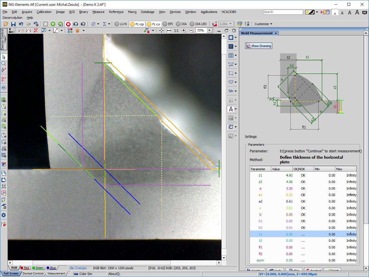
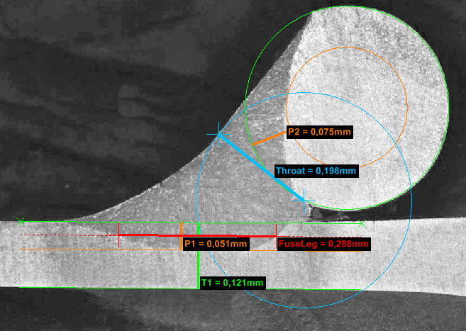
The module is a comfortable tool for measuring of individual weld parameters. The measurement proceeds step by step according to the prepared guide, procedures for fillet, lap and spot welds are available. Other procedures can be created for non-standard and user-defined weld geometries.
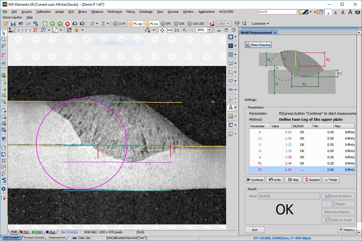
During the measurement, various auxiliary lines, circles, point lines, etc. are drawn into the image, they disappear once their purpose is fulfilled. In addition to measurement using the fixed wizard, anything can be measured separately using general measurement tools. Measurement of lengths can be extended to measure areas or defect sizes.
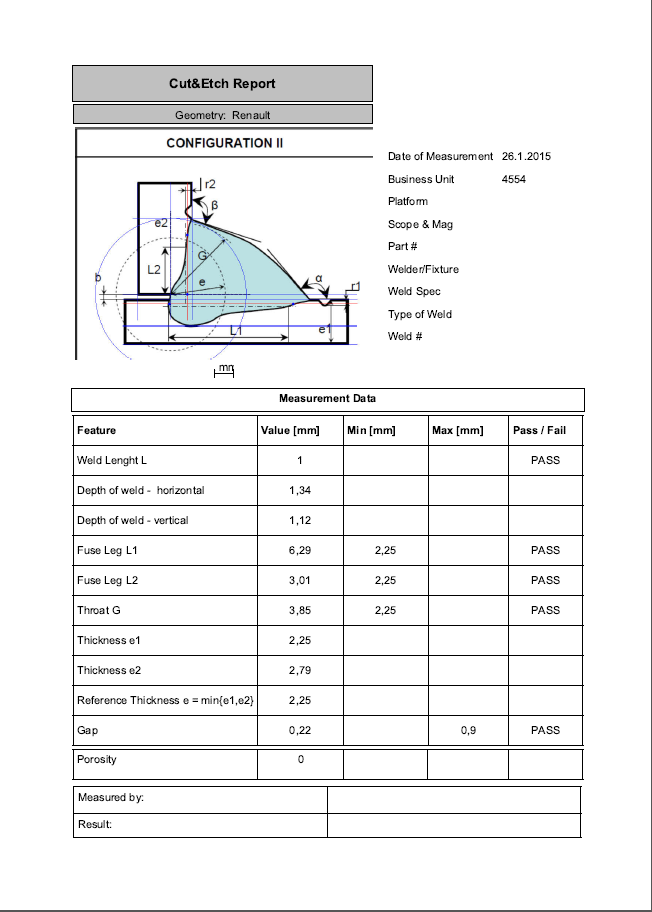
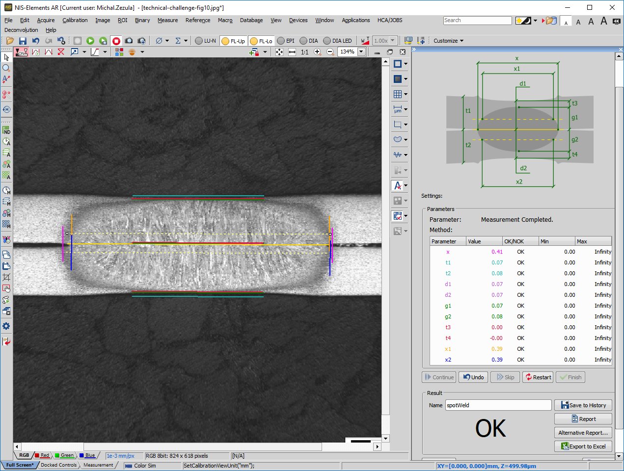
After the measurement is finished, the module creates a report. It usually includes:
-
a header containing information about the workplace, author, etc.
-
the evaluated image, possibly accompanied by a geometry drawing
-
a table with the measured data
-
optionally, an automatic evaluation can be added to determine whether or not the measured values meet the specified limits.
The report can be saved in the native NIS-Elements format (RPT) and / or exported to PDF or RTF. Data output can also be linked to MS Excel templates. Weld images can be saved in standard image formats (TIF, JP2, BMP, JPG) during or after the measurement or included in the report.
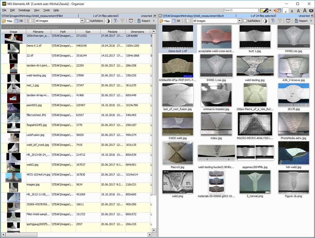
The NIS-Elements software includes an image organizer which meets basic requirements for image management including sorting, searching by parameters, etc. Different levels of user rights can be set in the system for greater security of the electronic data.. Optionally, the system can be adapted to the customer's needs to cooperate with MS SQL-based databases, information systems, etc.
A stereomicroscope, a macro-optic or a standard lens on a stand with illumination is suitable for acquisition of weld images.